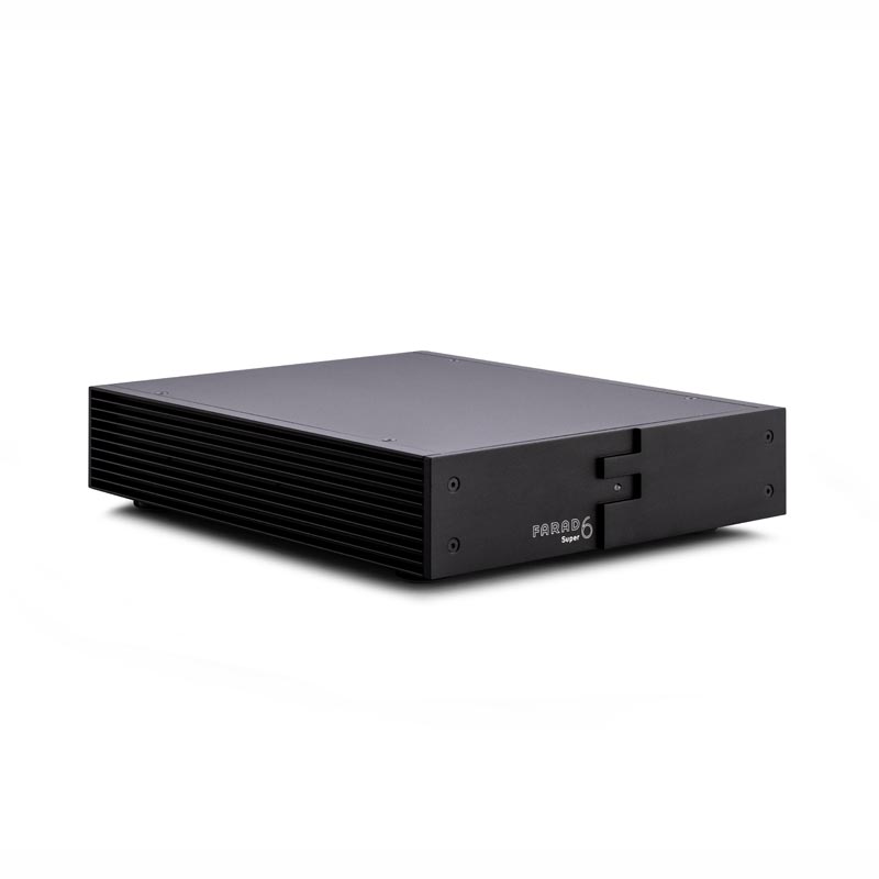
“The power to let music flow freely”

MY-HiEND
“After switching to Super6, the sound is more comprehensive and the subtleties are clearer in the soft and quite passages. Many deep and subtle details emerge from the original silky picture, and undulating dynamics are added, making the sound feel smoother and making the music more consistent and extensible.”
Anatomy of your Super6 PSU
Highlighting the fundamentals of it’s performance
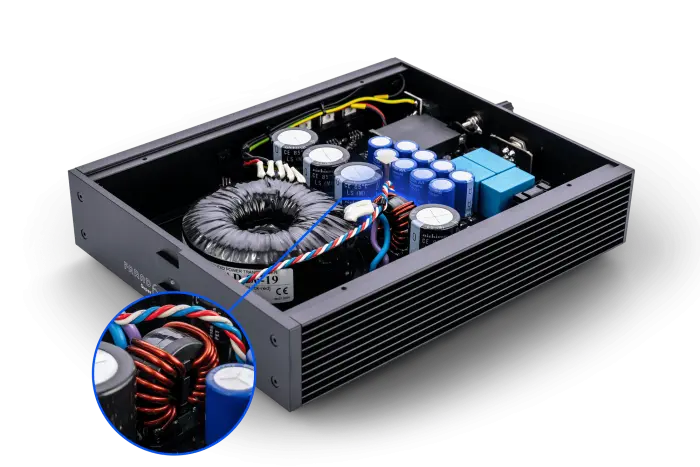
Hf Pi-filter smoothing section
Low ESR Capacitors and Hf common mode choke filtering reduce ripple and Hf noise from mains and rectifiers. In total tehre are 6 pi-filter sections in a Super6 to reduce Hf noise to a minimum before and after regulation. Low frequency noise (ripple) is fullly eliminated by the double regulation and supercapacitors.
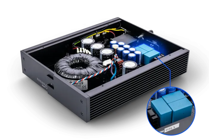
Foil Output Stage
The Super6 has a 150uF MKS foil capacitor output stage. MKS capacitors are used for stable operation and great sound quality whilst ESR is very low because of the absence of electrolytic capacitors. All of this provides an ultra-fast delivery of power, a pitch-black background whilst maintaining operation over the full bandwidth.
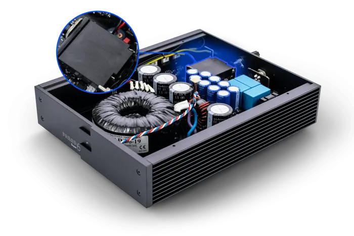
Thermal Magnetic Circuit Breaker
Standard fitted in the Super6, this TMCB is mocking conventions when it comes to musicality, flow, and musical reproduction in the most natural way. Spectacular in being non-spectacular. We simply adore it and are sure so will you!
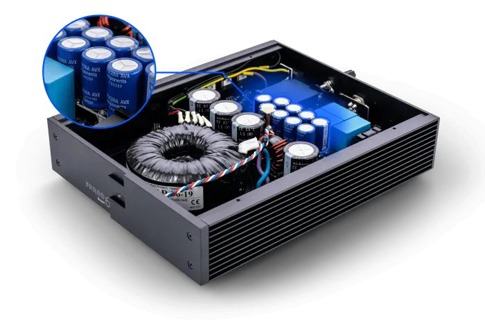
Super Capacitor Power Bank
Supercaps tuned to the voltage of the power supply provide a capacitance of 2.3F (2,300,000uF) to 8.3F (8,300,000uF), depending on voltage. This bank acts like a virtual battery, supplying the final low-noise regulation with total stable clean input power. The result is pure DC voltage with the lowest noise floor thinkable over the full bandwidth.
![]() TECHNICAL SPECIFICATIONS
TECHNICAL SPECIFICATIONS
Output voltage Capacitance Max power consumption
- 5 8.3F 75W
- 9 5.0F 100W
- 12 (or -12) 4.2F 120W
- 15 (or -15) 3.6F 135W
- 19 2.8F 160W
- 24 2.3F 180W
Any other voltage between 5V and 24V available on special request

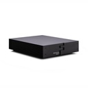
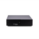
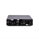
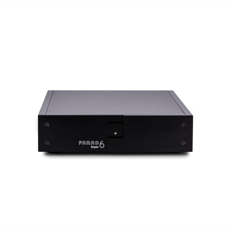
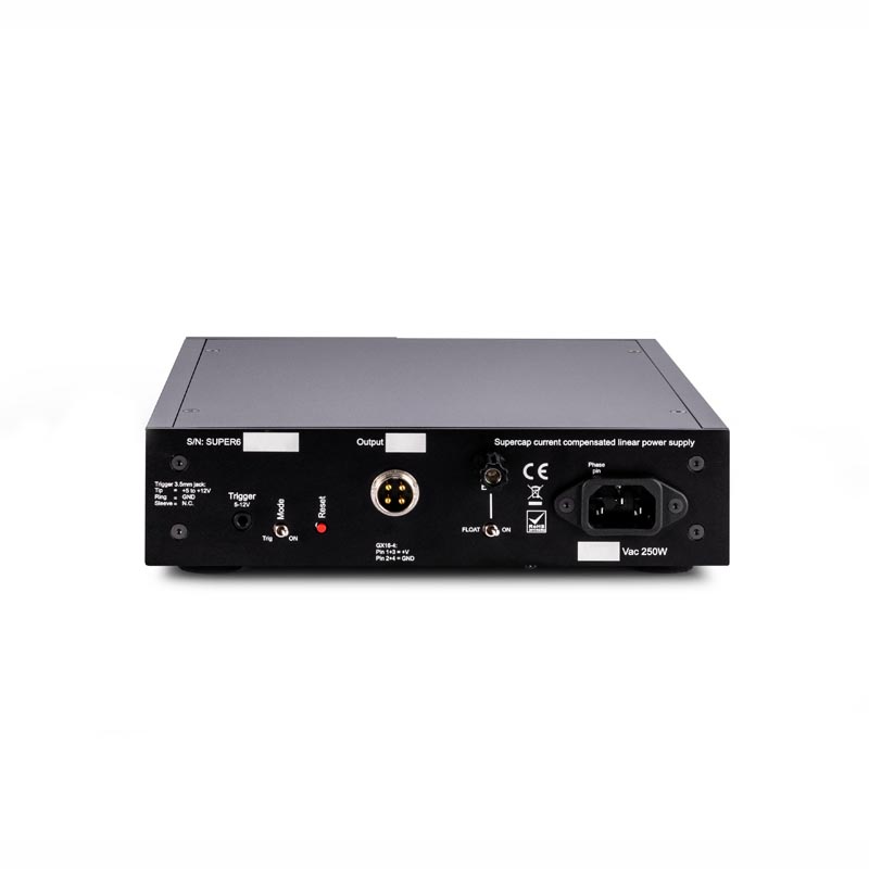
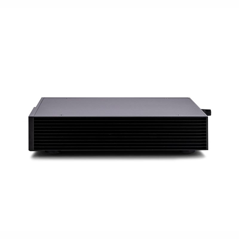
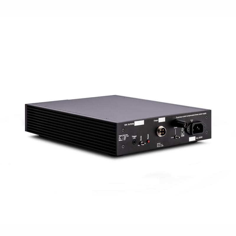
Front and back of the Super6 power supply, controls and connections
1) Indicator LED. The front LED has several modes
a) Solid blue: Power supply is ready, voltage present at output.
b) Solid blue and red (purple): AC input voltage too low, or output voltage too low (short), no critical error, turns into error (d) after 3 seconds.
c) Fading red: Power supply is charging supercapacitor banks at startup.
d) Flashing red: Power supply error. Led flashes fast and then slowly with error code.
e) No LED. Power supply is disabled or in reset, or TCB tripped.
2) DC output connector. We use a gold plated GX25-4 connector. Plus is connected to pin 1 and 3 and minus to pin 2 and 4. This output delivers the rated voltage (stated at position 4) at 10A maximum current.
3) Reset switch. This switch resets the power supplies microprocessor. After a reset the supply will start a new startup sequence. It can be used to reset the supplied device, or when changing between different devices. Also when an error has occurred and the supply needs restart.
4) Rated output voltage. In this box the factory fixed output voltage is noted.
5) Trigger. The Super6 can be trigger activated.
5a) Trigger mode: Trig means the supply is put standby and on by the trigger input. An active supply will show a blue led, standby mode will show a faded blue led. ON means the supply output is always active normally.
5b) Trigger input: Trigger input uses a 3.5mm stereo jack connector, +5V to +12V on the tip, and GND on the ring. The GND of the jack is not connected.
6) Mains voltage indication. When noted “115”, the power supply is configured for 110-120Vac, 50-60Hz voltage range. If noted “230”, the power supply is configured for 220-240Vac / 50-60Hz mains voltage range. “100” and “127” are configured for 100Vac and 127Vac input 50-60Hz.
7) Mains IEC connector. Place mains power cord at this connector. The power supply is optimized such that lowest leakage current will be present when AC phase is applied to the (L / phase pin) pin of the connector
8) Serial number. Always refer to this number in any communication with your dealer or Farad power supplies directly.
9) Earth connector. External earthing of the Super6.
9a) Float switch: The earth connector can be connected to the output GND by a 10R resistor parallel to a choke (ON), or disconnected to make a floating power supply (FLOAT). For safety line earth is always connected to the Super6 housing.
9b) Earth connector: You can connect an extern earth or earth box here, the earth connector takes a bare wire, small spade and banana.

Our latest content
Check out what's new in our company !